
2WD Models
1. Remove the rear wheels (see above).
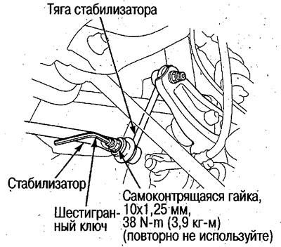
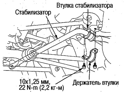
2. Disconnect the stabilizer links from the stabilizer.
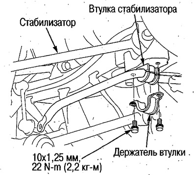
3. Remove bushing holders and stabilizer.
4. Install the stabilizer in the reverse order of removal.
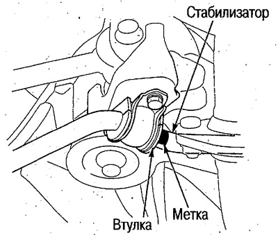
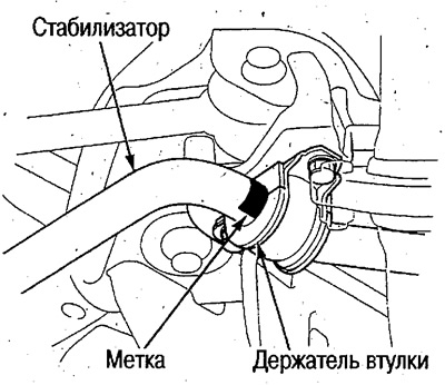
During installation, align the end of the sleeve with the mark.
See below for stabilizer link installation.
 |  |
4WD Models
1. Remove the rear wheels (see above).
2. Disconnect the stabilizer links from the stabilizer.
3. Remove bushing holders and stabilizer.
4. Install the stabilizer in the reverse order of removal.
During installation, align the end of the sleeve with the mark.
See below for stabilizer link installation.
Removal and installation of stabilizer rods
2WD Models
1. Remove the rear wheels (see above).
2. Disconnect the links from the stabilizer (see above).
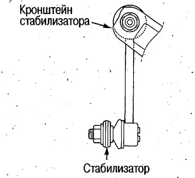
3. Disconnect the stabilizer links from the bracket and remove them.
4. Install in the reverse order of removal.
Connect the rods to the stabilizer in the following order:
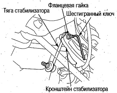
Set the ball joint pin of the rod to the middle position, connect the rod to the stabilizer and trailing arm and tighten the nut by hand.
Transfer the weight of the car to the stabilizer by lifting the suspension with a jack.
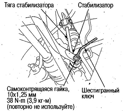
Lock the ball joint pin with a hex wrench and tighten each nut to the correct torque.
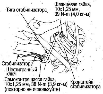
After 5 min. After tightening the self-locking nuts, re-tighten the stabilizer side nut to the correct torque.
4WD Models
1. Remove the rear wheels (see above).
2. Disconnect the links from the stabilizer (see above).
3. Disconnect the stabilizer links from the upper arm and remove them.
4. Install in the reverse order of removal.
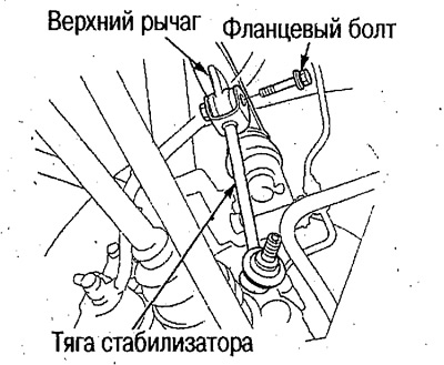
Connect the rods with the stabilizer in the following order:
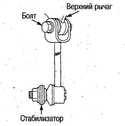
- Connect the rod to the upper arm and tighten the bolt by hand.
- Set the ball joint pin of the rod to the middle position, connect the rod to the stabilizer and tighten the nut by hand.
- Transfer the weight of the car to the stabilizer by lifting the suspension with a jack.
- Lock the ball joint pin with a hex wrench and tighten the nut to the required torque.
- Tighten the mounting bolt on the upper arm side to the required torque.
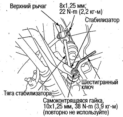
After 5 min. After tightening the self-locking nuts, re-tighten the stabilizer side nut to the correct torque.
Removal and installation of the upper arm
2WD Models
1. Remove the rear wheels (see above).
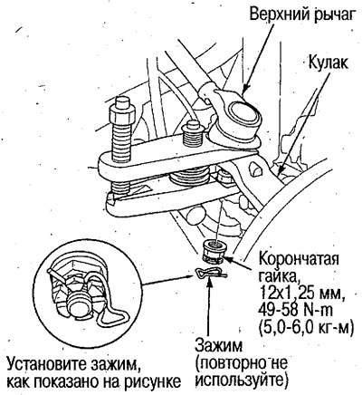
2. Disconnect the upper arm from the knuckle.
 |  |
3. Remove the upper arm bolt and remove the upper arm.
4. Install the upper arm in the reverse order of removal.
Connect in the following order:
- Connect all components and tighten bolts/nuts by hand.
- Transfer the vehicle's weight to the suspension by raising the suspension with a jack.
- Tighten the bolts/nuts to the required torque.
5. Check and adjust wheel alignment (see above).
4WD Models
1. Remove the rear wheels (cm; higher).
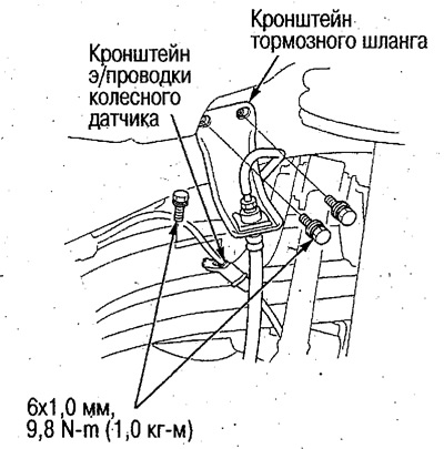
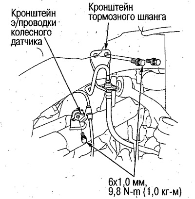
2. Disconnect e/conducting of the wheel gauge from the top lever.
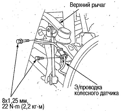
3. Disconnect the upper arm from the stabilizer link.
4. Remove the brake hose bracket and wheel sensor e/wiring bracket.
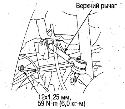
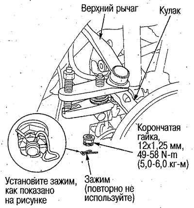
5. Disconnect the upper arm from the knuckle.
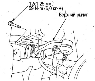
6. Remove the upper arm bolt and remove the upper arm.
7. Install the upper arm in the reverse order of removal.
Connect in the following order:
- Connect all components and tighten bolts/nuts by hand.
- Transfer the vehicle's weight to the suspension by raising the suspension with a jack.
- Tighten the bolts/nuts to the required torque.
8. Check and adjust wheel alignment (see above).
Removal and installation of the trailing arm
1. Remove the rear wheels (see above).
2. Disconnect the parking brake cable from the trailing arm (see above).
3. Disconnect the trailing arm from the knuckle and body and remove it.
4. Install the trailing arm in the reverse order of removal.
Connect in the following order:
- Connect all components and tighten bolts/nuts by hand.
- Transfer the vehicle's weight to the suspension by raising the suspension with a jack.
- Tighten the bolts/nuts to the required torque.
5. Check and adjust wheel alignment (see above).
Removal and installation of the leading lever
1. Remove the rear wheels (see above).
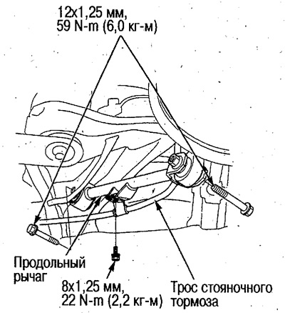
2. Disconnect the leading lever from a fist and a body and remove it.
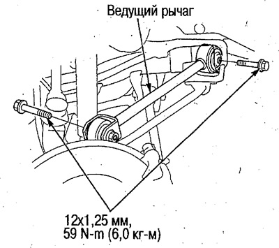
3. Install in the reverse order of removal.
Connect in the following order:
- Connect all components and tighten bolts/nuts by hand (see fig. on the trail. page).
- Transfer the vehicle's weight to the suspension by raising the suspension with a jack.
- Tighten the bolts/nuts to the required torque.
4. Check and adjust wheel alignment (see above).
Removal and installation of the lower arm
1. Remove the rear wheels (see above).
2. Disconnect the lower arm from the knuckle and body and remove it.
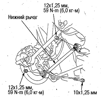
3. Install in the reverse order of removal.
Connect in the following order:
- Connect all components and tighten bolts/nuts by hand.
- Transfer the vehicle's weight to the suspension by raising the suspension with a jack.
- Tighten the bolts/nuts to the required torque.
4. Check and adjust wheel alignment (see above).
Removal and installation of the operating lever
1. Remove the rear wheels (see above).
2. Disconnect the control arm from the knuckle and body and remove it.
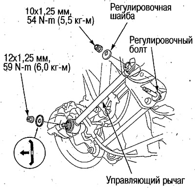
3. Install in the reverse order of removal.
Connect in the following order:
- Connect all components and tighten bolts/nuts by hand.
- Transfer the vehicle's weight to the suspension by raising the suspension with a jack.
- Tighten the bolts/nuts to the required torque.
4. Check and adjust wheel alignment (see above).