
Examination
1. Depress the foot brake pedal and verify that the brake lights on the rear combination lamp assemblies are working properly.
2. If the brake lights do not work, check the condition of the appropriate fuse (see chapter Onboard electrical equipment). Also check the condition of the brake lamp filaments in both rear combination lamps, as well as the high level brake lamp.
3. If the lamps and fuse are in order, look for the sensor-switch installed at the top of the foot brake pedal.
4. Disunite an electric socket of the gauge switch.
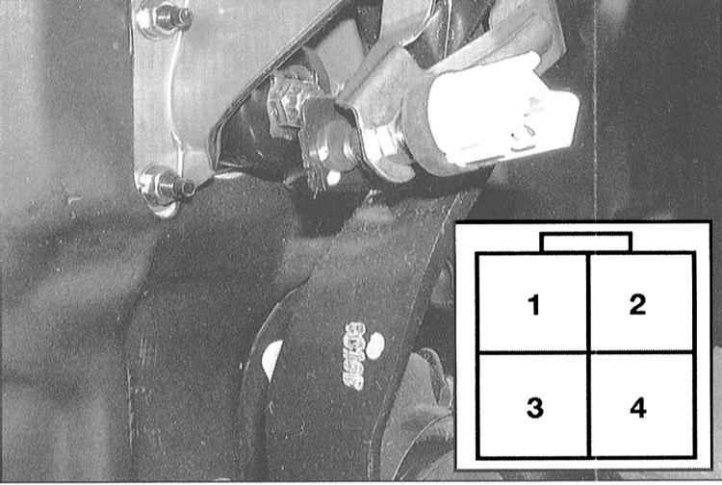
5. Check continuity between terminals 2 and 3 of the connector. With the foot brake pedal depressed, conduction should take place, but not with the foot brake pedal released.
6. Also check the continuity between terminals 1 and 4 - the opposite should be true here, i.e. when the pedal is depressed, there should be no conduction, and vice versa.
7. At negative result of checks replace the gauge switch.
Replacement
1. Disconnect the electrical wiring from the sensor-switch.
2. Loosen the locknut on the pedal-facing side of the sensor-switch, then unscrew the latter from its support bracket.
3. Installation is carried out in the reverse order.
Adjustment
1. Loosen the locknut of the sensor-switch and unscrew the latter so that its plunger rests on the foot brake pedal.
2. Loosen the pusher locknut and, turning the latter with pliers, properly adjust the height of the pedal position (see Specifications).
Note. The measurement should be taken from the pedal pad to the floor panel (not to the rug!).
3. Retighten locknut firmly.
4. Screw the sensor-switch into the bracket so that its plunger is completely recessed (the threaded tip rests on the pedal lever pad), then back it out 1/2 turn and tighten the lock nut firmly.
5. Depress the foot brake pedal by hand and measure its free play. Compare the measurement result with the requirements of the Specifications. Make sure that the brake lights work properly when the brake pedal is depressed.