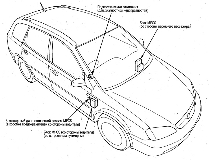
Location of components
The MPCS system includes two blocks (driver side and front passenger side), which improve the performance of each previously used unified block (control units for power windows, outside rear-view mirrors, door locks and a remote control for door locks).
In addition, all units are interconnected by communication lines, the system has a self-diagnostic function, which simplifies its maintenance.
Self-diagnosis function
Mode 1
Self-diagnosis of each unit (driver side and front passenger side) and communication lines between units is carried out according to fault codes (DTC).
Approximately 1 sec. after entering diagnostic mode 1, the fault code is displayed, and then after approx. 3 sec. the following fault code is displayed.
The transition to mode 2 is made by opening the diagnostic connector for 5-10 seconds. and subsequent reclosing.
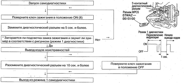
If trouble codes are not displayed, check the continuity between pin #1 of the diagnostic connector and «weight», as well as continuity between pin No. 3 of the diagnostic connector and pin A15 of the fuse box on the driver's side.
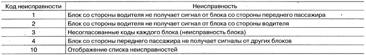
Fault codes
Below are the fault codes corresponding to the number of times the ignition key backlight is turned on and the sound of the buzzer.
Mode 2
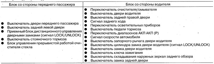
By actuating each block (switches, sensors, etc.) the serviceability of these circuits is determined by the operation of the backlight of the ignition switch and the sound of the buzzer.
(The check can be performed in the same way on the input signals. About checking individual switches, sensors, etc. see the description of the respective systems.)
In mode 1, open the diagnostic connector for 5-10 seconds, and then close it again, then the system will go into self-diagnosis mode 2. (The buzzer and ignition switch light will work during the transition to mode 2, as shown in the figure).
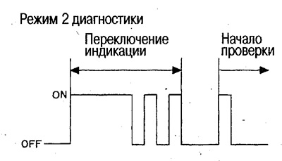
To exit this mode, open the diagnostic connector for 10 seconds. or more, or turn the ignition key to the OFF position.
If the components listed in the table are in good condition, the ignition switch illumination and the buzzer will work once.
- If there is a fault somewhere in the circuit, the backlight does not come on.
- If the backlight does not come on, refer to the appropriate system test description.
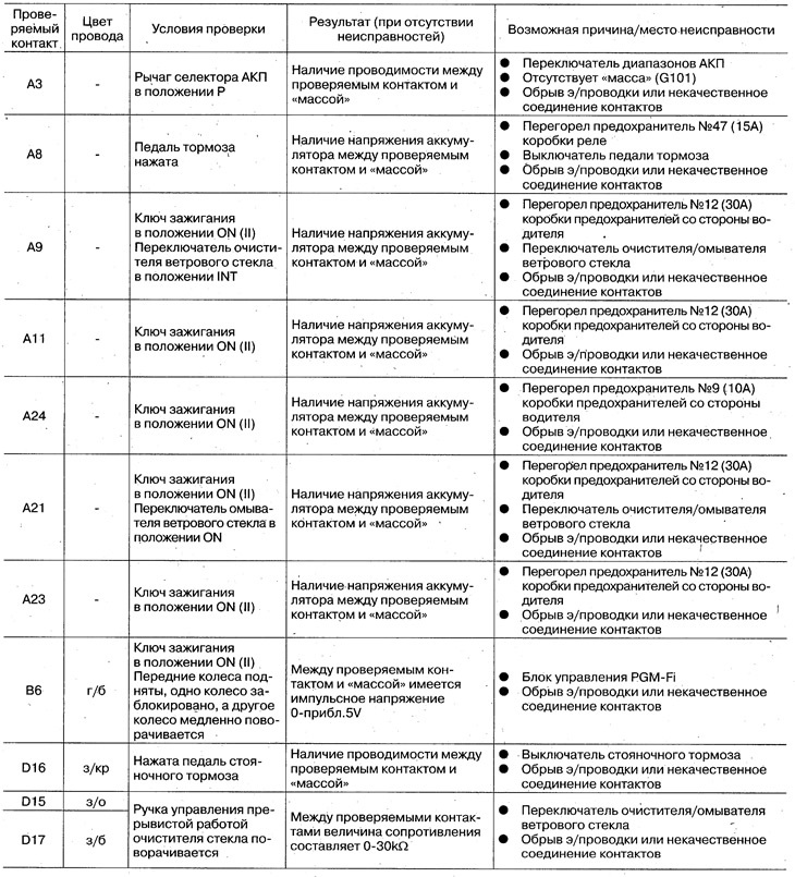
Component Input/Output Table
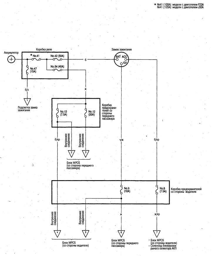
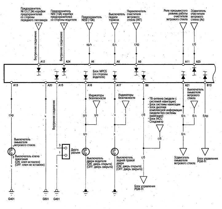
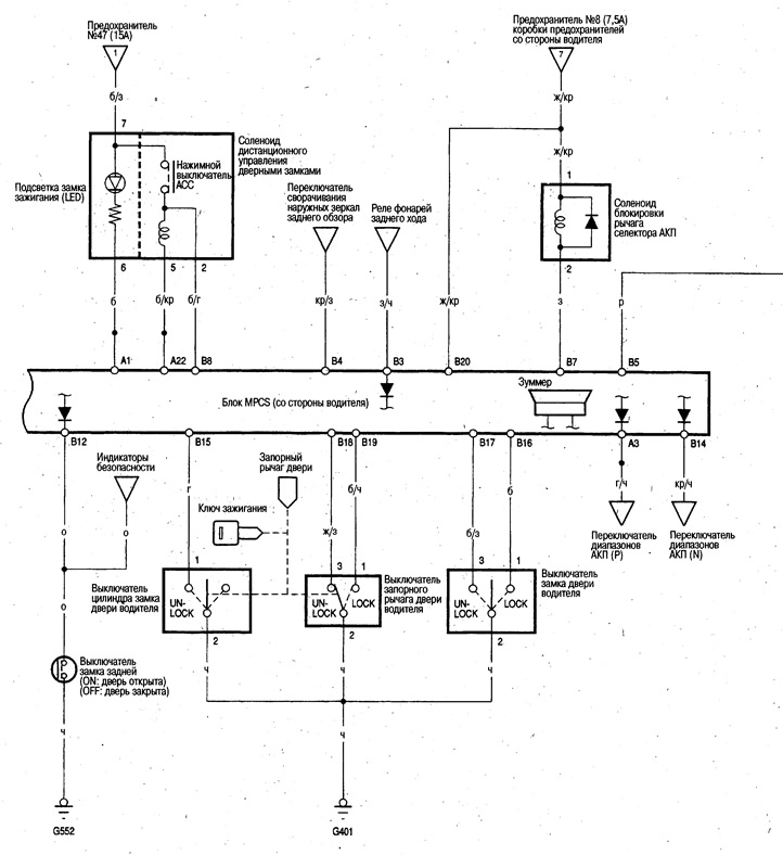
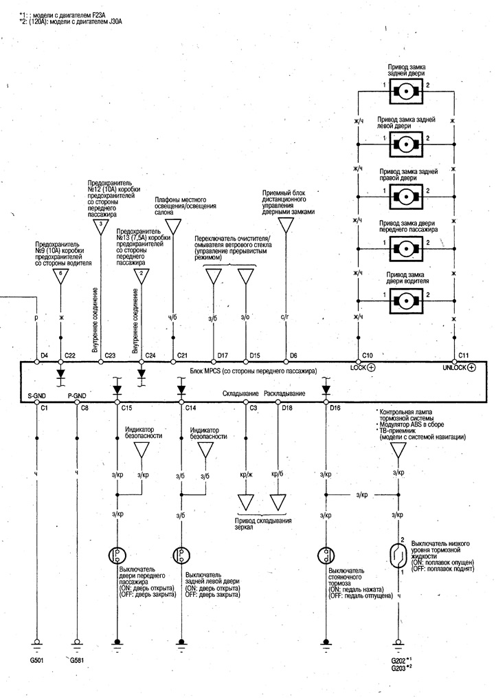
Wiring diagram
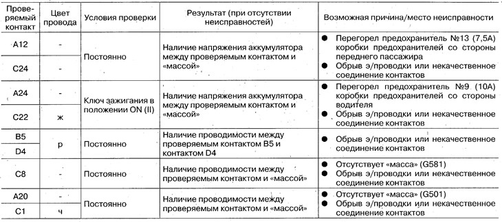
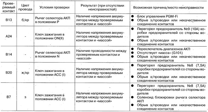
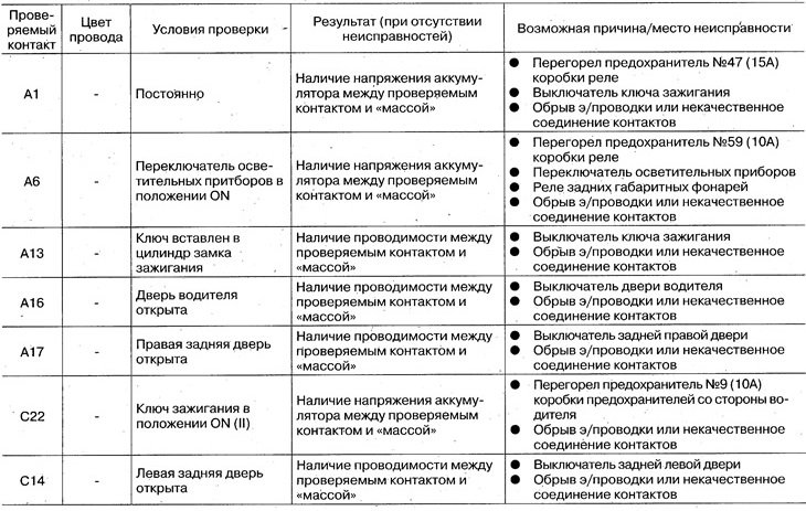
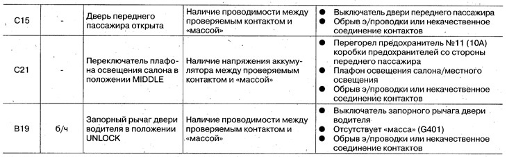
Checking input signals
Driver side MPCS unit
If there are components of an additional passive safety system nearby, during work see ch. Additional passive safety system (SRS).
1. Remove the side cover from the dashboard side and the right side trim of the hood.
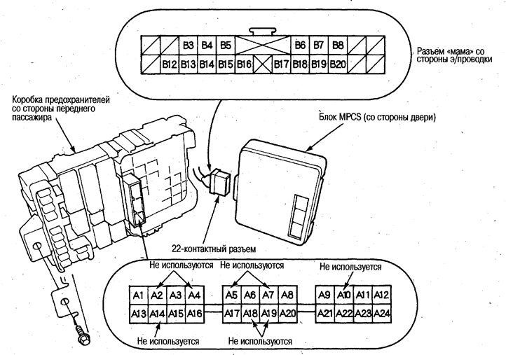
2. Turn off a bolt and remove a box of safety locks from outside the driver.
3. Disconnect the 22-pin connector from the block.
4. Remove the block from the fuse box.
5. Check input signals from each system. If all signals are normal and the system does not work, replace the MPCS unit on the driver's side.
MPCS unit, front passenger side
1. Remove the glove box (see ch. Body).
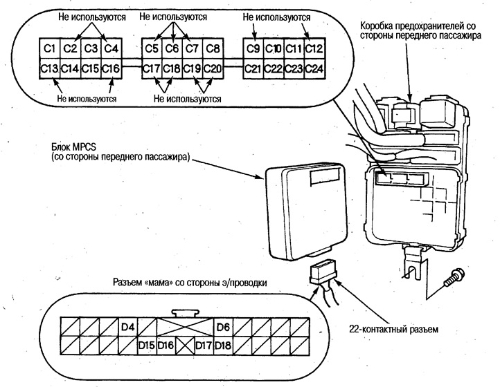
2. Turn off a bolt and remove a box of safety locks from outside the forward passenger.
3. Disconnect the 22-pin connector from the block.
4. Remove the block from the fuse box.
5. Check input signals from each system. If all signals are normal and the system does not work, replace the MPCS unit on the front passenger side.
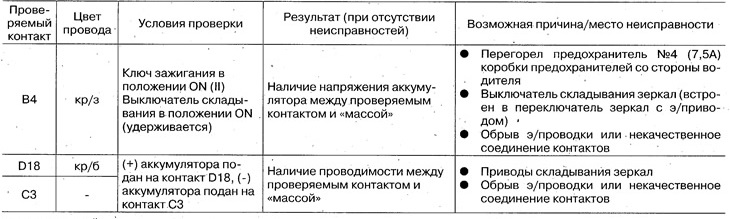
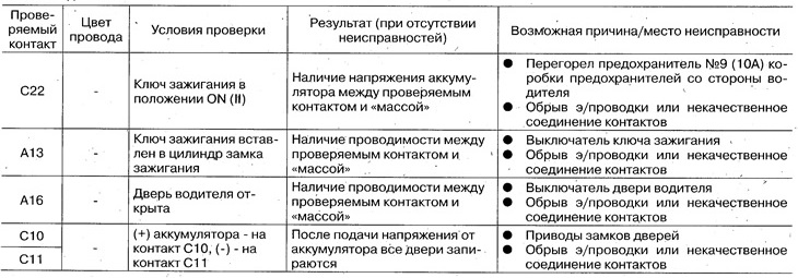
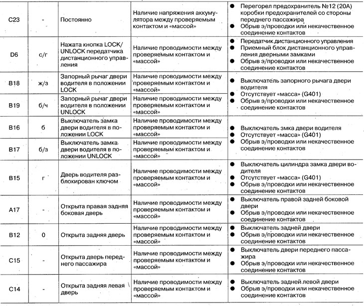
Checking input signals
MPCS
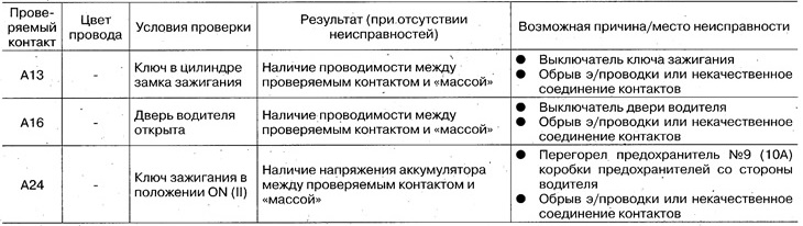
Ignition key reminder system
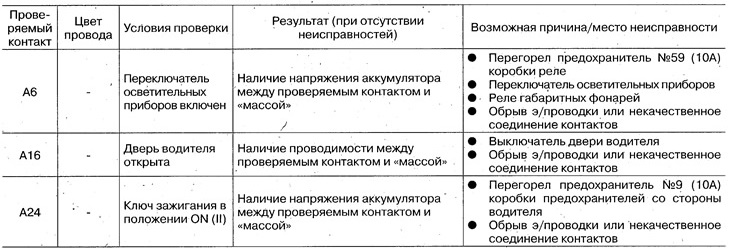
Light fixture reminder system
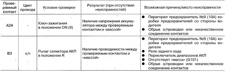
Reversing warning system
Ignition key lock system

Selector lever lock system
Folding door mirror system
Locking the doors
Interior lighting control system
Control system for intermittent wiper operation based on vehicle speed