
Attention. Observe fire safety regulations.
1. Check the serviceability of the fuse (10A) for the instrument cluster illumination, installed in the fuse box on the driver's side.
- If the fuse is good, check for a break in the electrical wiring between fuse #9 and the instrument cluster.
- If the fuse is blown, replace it with a new one and check the wiring between fuse #9 and the instrument cluster for short circuit. Also check the various components for internal short circuit (see chapter Body).
2. Remove the rear seat, fold up the floor covering and remove the inspection hole cover.
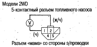
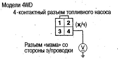
3. Disconnect the 5-pin (4-pin on 4WD models) fuel pump connector.
4. Turn the ignition switch to the ON (II) position and measure the voltage between terminals #1 and #2 of the 5-pin connector (on 4WD models, between terminal #4 and ground).
 |
 |
If the voltage is approx. 5-8V, perform the check according to item 5.
If there is no voltage, check for an open in the yellow/black wire between the fuel pump and the instrument cluster and the black wire between the fuel pump and ground G552.
5. Turn the ignition key to the OFF position.
6.
2WD models:
Remove the fuel pump from the fuel tank (see above).
Do not damage the float and block.
4WD models:
Remove the fuel pump and intermediate fuel pump (see above). Be careful not to damage the float or block.
7.
2WD models:
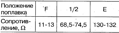
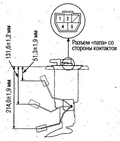
Check that the resistance between terminals No.1 and No.2 of the 5-pin fuel pump connector changes smoothly during the smooth raising and lowering of the float, and then measure the resistance at the float positions indicated below.
 |
 |
4WD models:
Check that the resistance between terminals No.3 and No.2-4 of the 4-pin fuel pump connector changes smoothly during the smooth raising and lowering of the float, and then measure the resistance at the float positions indicated below.
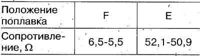 |
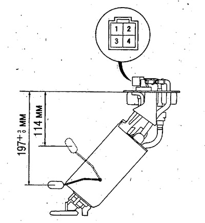 |
Check that the resistance between terminals No.1 and No.2 of the 2-pin connector of the intermediate fuel pump changes smoothly during the smooth raising and lowering of the float, and then measure the resistance at the float positions indicated below.
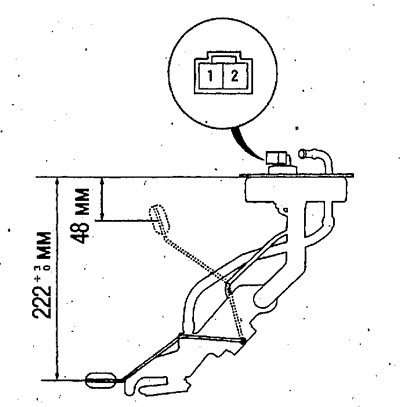 |
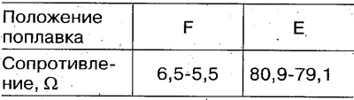 |
If the sending unit does not meet the above requirements, replace it (see above) (on 4WD models, replace the fuel pump and intermediate fuel unit assembly).
If there are no faults, perform the check according to item 8.
8. Connect the 5-pin (4-pin on 4WD models) fuel pump connector.
9. Fix the float in the "F" position and turn the ignition key to the ON (II) position.
Caution: To avoid damaging the fuel gauge, do not hold the float in the "F" position for a long time.
10. Make sure that the fuel gauge needle is in the "F" position.
If the arrow does not point to "F", replace the instrument cluster.
If the arrow points to "F", the fuel gauge and fuel block are in good working order.
Material obtained from the website: www.hondabook.ru