Note:
- Install in the reverse order of removal.
- The tightening torques are indicated in the text.
- After installation, calibrate the starting clutch.
1. Raise the vehicle.
2. Remove the protection covers.
3. Remove the drain plug "A", and drain the CVT fluid. Install plug with new gasket "IN".
4. Disconnect the negative battery terminal and then the positive one.
5. Remove bracket, tray and battery.
6. Remove the air filter and air duct.
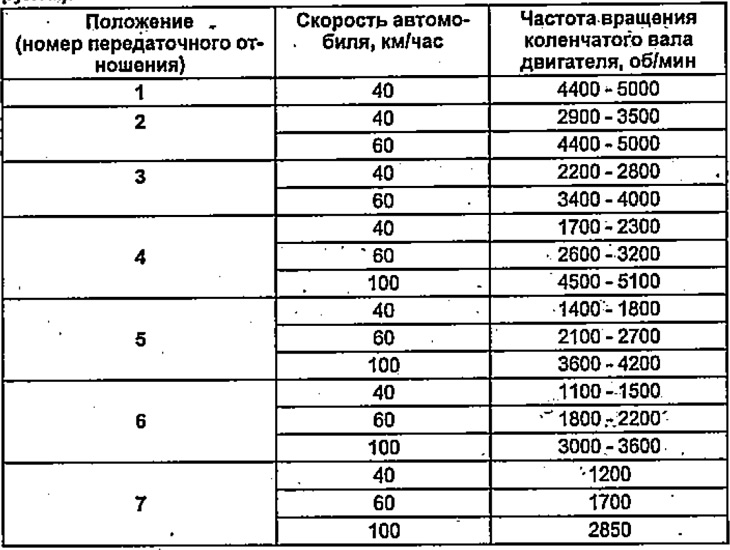
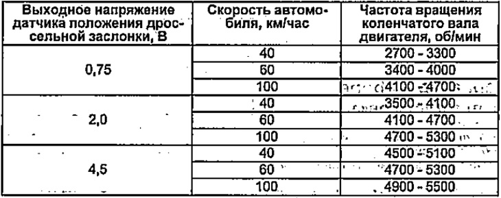
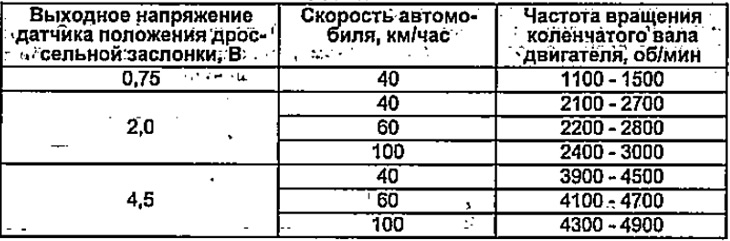
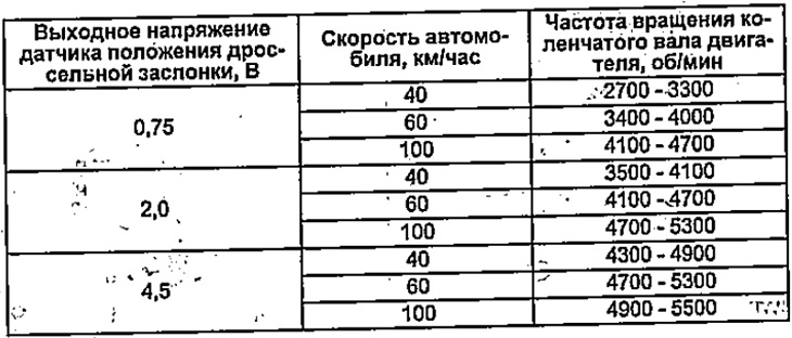
Table. Road test. L13A since 2003, with manual ratio change mode. Range "L".
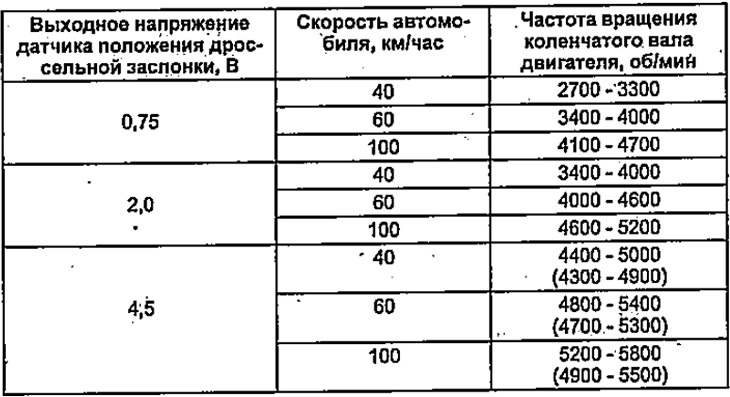
() - except KM/KR.
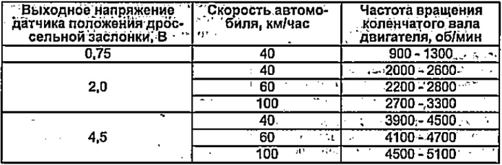
Manual gear change mode (left-hand drive models, except for KM/KR).
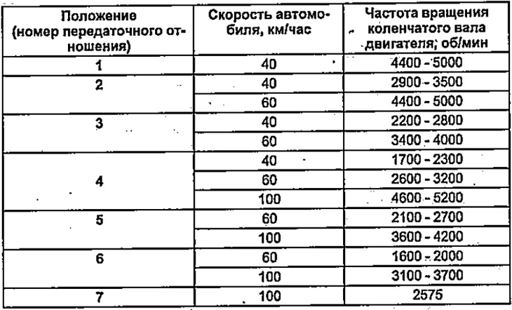
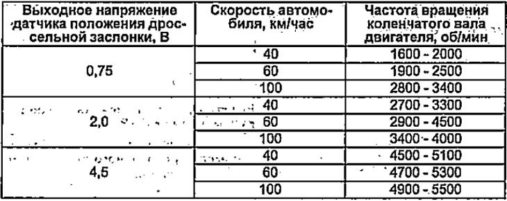
Manual gear change mode (right hand drive models).
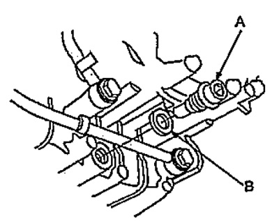
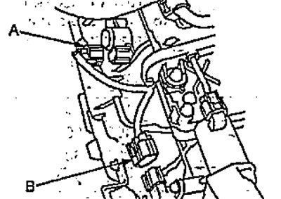
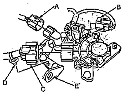
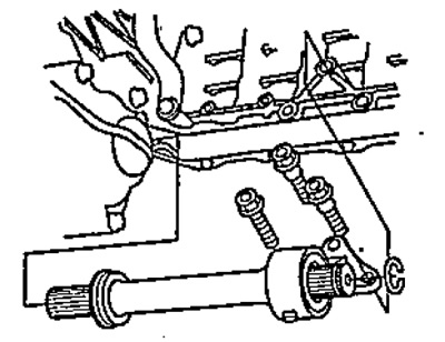
7. Disconnect connector "A" start inhibit solenoid valve and connector "IN" drive pulley speed sensor.
8. Disconnect: the connectors of the following items:
- "A" solenoid valve control starting clutch;
- "IN" pulley pressure control solenoid valve;
- "WITH" speed change solenoid valve.
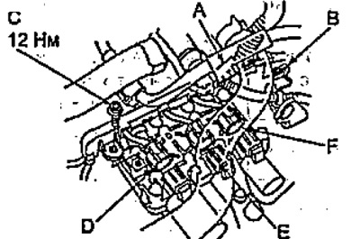
9. Remove the bolt "D", remove the cover "E" wiring harness and bracket "F".
10. Remove the latch "A" battery wires from bracket "IN", then remove the bracket "WITH".
11. Remove a radiator hose from a clamp.
12. Remove cotter pin "A" and puck "IN".
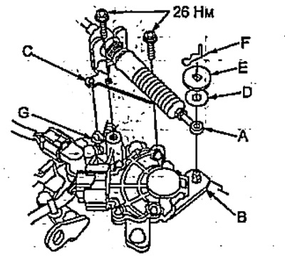
Table. Road test. L13A since 2003, KQ models without manual ratio change mode. Range "D".
Range "S".
Range "L".
L13A since 2003, no manual ratio change mode. Range "D".
Range "S".

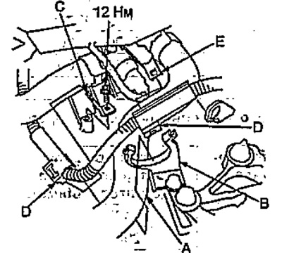
13. Remove bracket "WITH", disconnect the cable "D" from the lever "E".
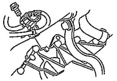
14. Disconnect the connector "A" selector position sensor and remove the retainer "IN" wiring harness with bracket "C".
15. Disconnect the connector "D" Pulley driven speed sensor connector "E" variator speed sensor.
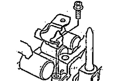
16. Disconnect the vacuum hose from the EVAP valve and unscrew the intake manifold mounting bolt, then move the cooling system hose.
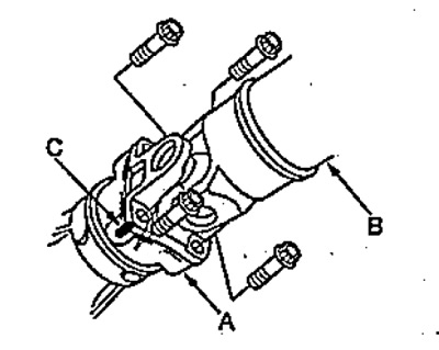
17. Install the hook "A" on bracket "B" air filter.
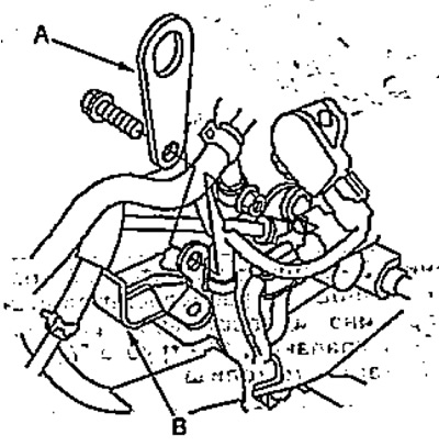
18. Turn away bolts of fastening of a variator.
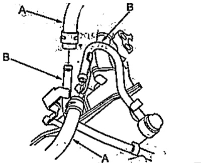
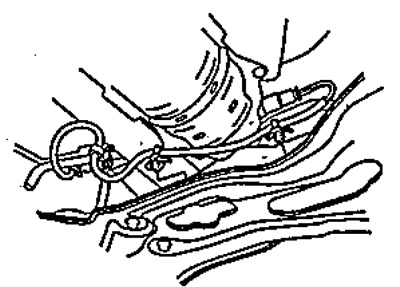
19. Disconnect the hoses "A" variator working fluid cooler.
Note:
- Rotate both the hose and install the plugs to prevent fluid from escaping.
- Check for leaks in the CVT fluid cooler line "IN".
Table. Road test. L13A since 2003, no manual ratio change mode. Range "L".
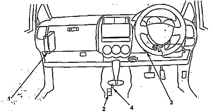
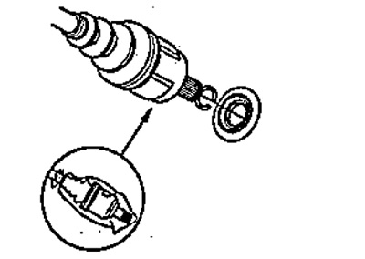
The location of the elements of the selector and key blocking system in the ignition lock.
1 - variator control unit,
2 - selector lock solenoid valve,
3 - electromagnetic riveter for blocking the ignition key,
4 - position sensor "R" (since 2003).
20. Loosen the hub nut "A". Using a plastic hammer, remove the drive shaft "IN" from the hub.
Note: Disconnect the lower ball joint.
- Tightening torque - 180 Nm
21. Loosen the nut "E" and disconnect the anti-roll bar.
- Tightening torque - 29 Nm
22. Remove cotter pin "F", unscrew the nut "G" and disconnect the tip "D" tie rod from knuckle "I".
- Nut tightening torque "G" - 59 Nm
23. Disconnect the lower arm from the knuckle.
24. Turn away bolts of fastening of the steering mechanism, remove an arm and the amplifier located in the right part of the steering mechanism.
- Tightening torque - 49 Nm
2WD.
4WD.
25. Turn away an arm and bolts of fastening of the left part of the steering mechanism.
2WD.
4WD.
26. Tilt the steering mechanism and suspend it from the body.
27. (4WD) Disconnect the wire harness clips.
28. (4WD)
Disconnect the propeller shaft from the transfer case.
Note: Mark the flanges.
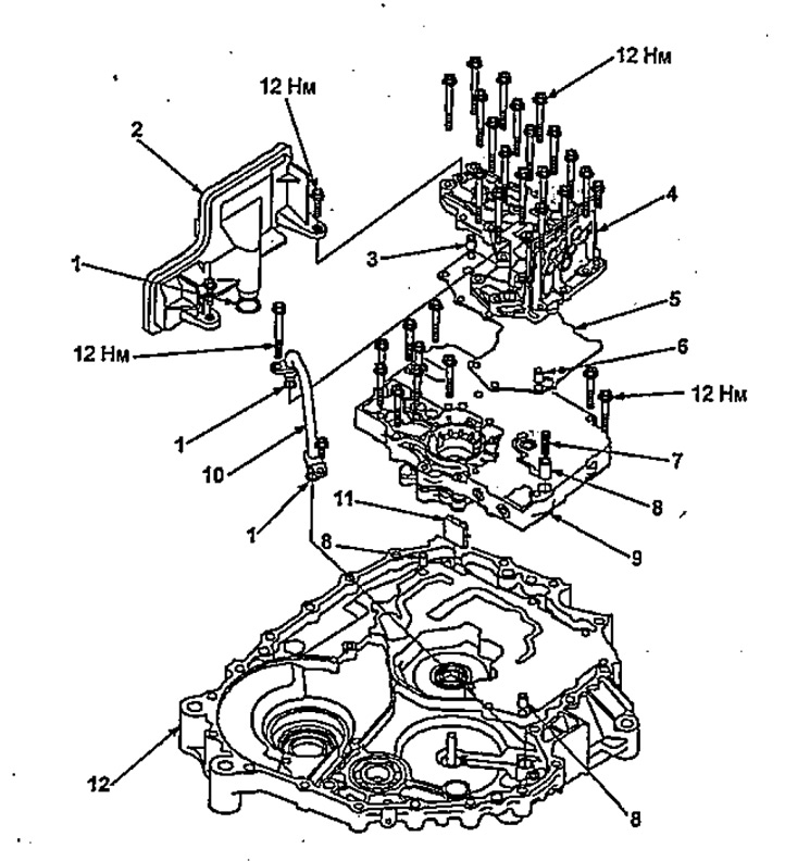
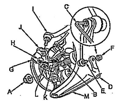
Filter replacement.
1 - ring seal,
2 - variator filter,
3 - guide pin,
4 - valve block cover,
5 - distribution plate,
6 - guide pin,
7 - spring of the hydraulic accumulator of the starting clutch,
8 - hydraulic accumulator,
9 - valve block,
10 - tube "A" variator working fluid,
11 - magnet,
12 - flywheel housing.
29. Turn away bolts of fastening of a back arm.
2WD.
4WD.
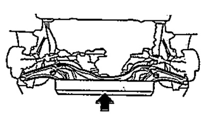
30. Install the stand through the wooden beam (100x100x1000mm) under the front suspension.
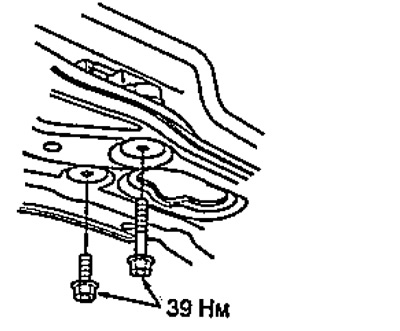
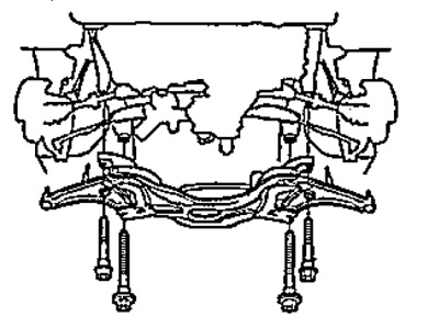
31. Turn away four bolts of fastening and remove a stretcher.
- Tightening torque - 93 Nm
32. Remove the drive shaft bracket.
- Tightening torque - 10 Nm
33. Remove drive shafts.
Note:
- Lubricate the drive shaft splines with engine oil and wrap the inner joint with a plastic bag.
- Install a new retaining ring.
34. (4WD)
Remove intermediate shaft.
- The tightening torque of the mounting bolts is 40 Nm
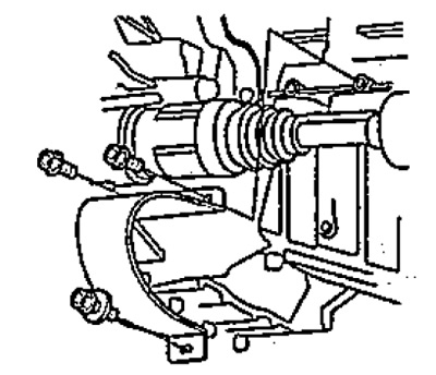
35. Remove the oxygen sensor bracket and connector from the flywheel housing.
- Tightening torque - 12 Nm
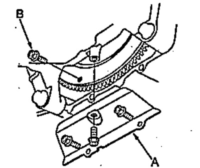
36. Remove the cover "A" flywheel and, turning the flywheel, unscrew the six bolts "IN" flywheel mountings.
- Tightening torque - 12 Nm
37. Install the stand under the variator.
39. Remove the wire "A" masses.
- Tightening torque - 12 Nm
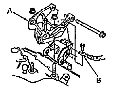
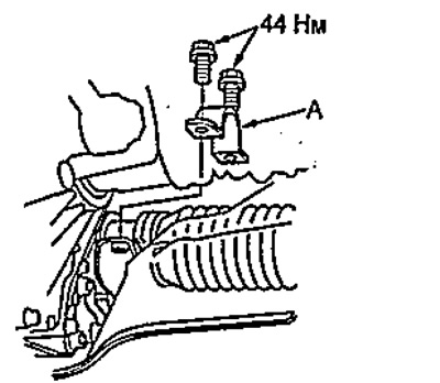
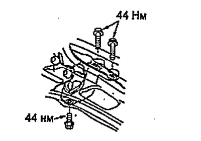
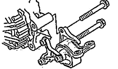
38. Remove the bolt "IN" and fastening nuts and remove the bracket "WITH" supports.
Torque:
- nuts - 49 Nm
- bolts - 44 Nm
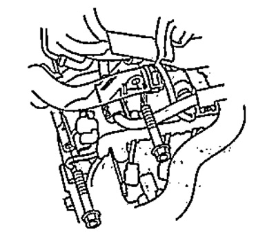
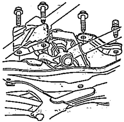
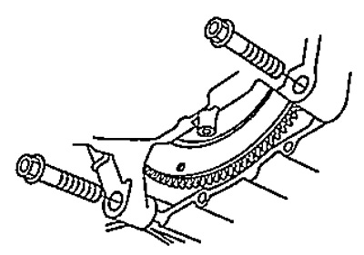
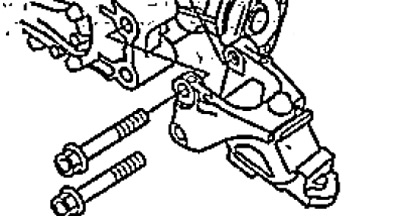
39. Turn away bolts of fastening of a case of a variator shown in drawing.
- Tightening torque - 64 Nm
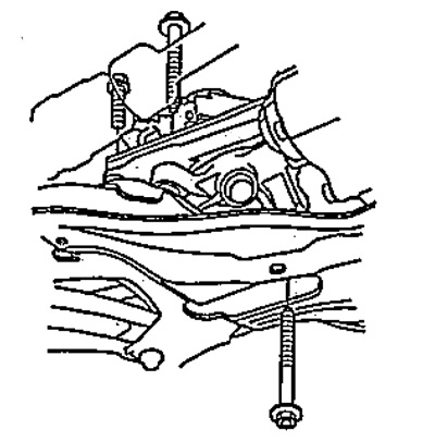
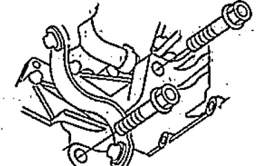
40. Turn away bolts of fastening located in the back lower part of a variator.
- Tightening torque - 64 Nm
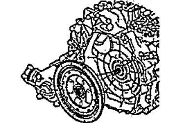
41. Remove the variator from the engine.
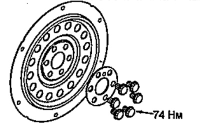
42. Remove the flywheel.
Note: When installing, apply high temperature grease to the motor output shaft splines.
43. Remove the air filter housing bracket.
- Tightening torque - 22 Nm
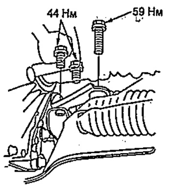
44. Remove the rear support of the power unit.
- Tightening torque - 59 Nm
2WD.
4WD.
45. Replace plate if necessary "A" flywheel drive.