
Checking the rectifier unit
Note: Disconnect the rectifier unit from the stator.
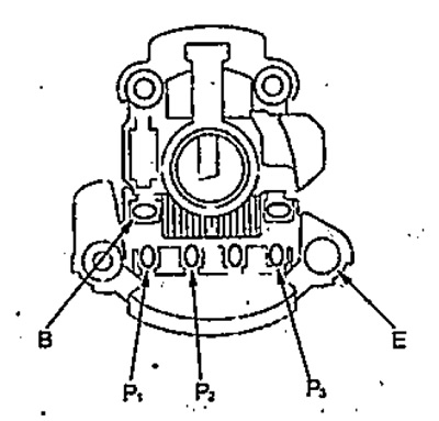
Check the continuity between the terminals shown below.
Reverse the polarity and measure the resistance again. Make sure that the conductivity is unidirectional.
- Between terminals — B - P (P ₁, P ₂, P ₃)
- Between terminals — E - P (P ₁, P ₂, P ₃)
Note: at terminals B, P ₁, P ₂, P ₃ check the conductivity together with the soldering points.
Checking the brush length
1. Measure the length of the brush.
- Nominal length - 19 mm
- Minimum length - 5 mm
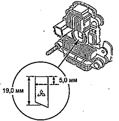
2. If the brush length is less than the minimum, unsolder the old brush and replace it with a new one.
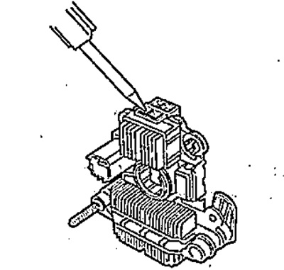
Replacing the rear bearing
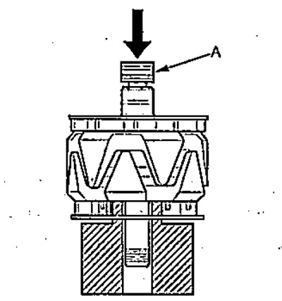
1. Remove the bearing using a puller.
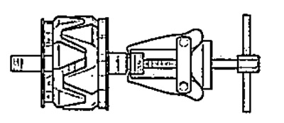
2. Using a hand press, install the new bearing "A".
Stator check
Note: Disconnect the rectifier unit from the stator.
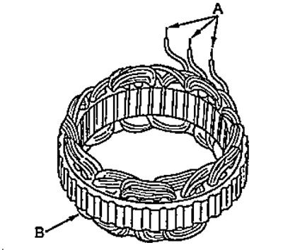
1. Check for continuity between the stator terminals (A).
2. Make sure there is no continuity between terminals (A) and stator (B).
Checking the rotor
1. Check the resistance between the contact rings.
- Nominal resistance - 1.8-2.1 mm
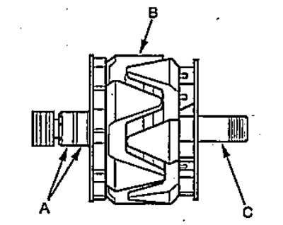
2. Make sure there is no conductivity between the slip rings and the rotor.
3. Make sure there is no conductivity between the slip rings and the rotor shaft.
[The original is located on the website: Hondabook.ru]