
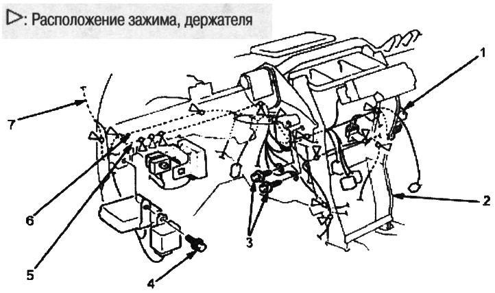
1. inertia switch; 2. steering bracket beam; 3. ground bolt, 6x10 mm, 9.8 Nm (1.0 kgf/m); 4. 6x10 mm, 9.8 Nm (1.0 kgf/m); 5. main harness; 6. SRS harness; 7. interior harness
This area contains the Supplemental Restraint System (SRS) components. Review the SRS component locations, precautions, and procedures before performing repairs or maintenance.
Note:
- When pressing components with a flat-head screwdriver, wrap it with protective tape to prevent damage and apply tape to adjacent components.
- When removing and installing the instrument panel, it is a good idea to have an assistant.
- Avoid scratching the instrument panel and adjacent components.
- Wear protective gloves.
- The picture shows a left-hand drive model; the arrangement on the right-hand drive model is symmetrical.
1. Remove the instrument panel (see above).
2. Disconnect the main harness, SRS harness and cabin harness from the steering bracket beam.
3. Loosen the bolts, then remove the steering bracket beam.
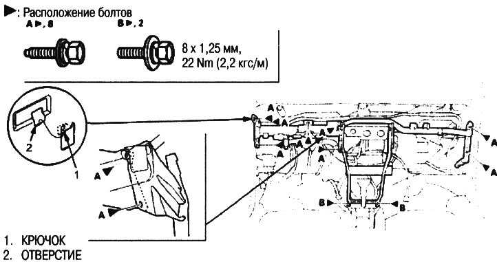
4. Installation is carried out in the reverse order of removal, taking into account the following:
- Make sure that the instrument panel wiring harness and steering bracket beams are not pinched
- Connect the connectors securely.
[Material obtained from the website: HONDABOOK.ru]