
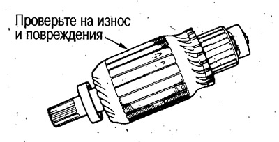
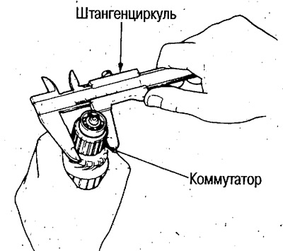
2. Measure the outer diameter of the commutator and if the wear is greater than the limit, replace the rotor. -
Commutator outer diameter:
- Standard: 28.0-28.1 mm
- Limit: 27.5 mm
3. Using an indicator, measure the commutator runout and, if it is greater than the limit, replace the rotor.
 |
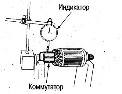 |
Commutator beating:
- Standard: less than 0.02mm
- Limit: 0.05 mm
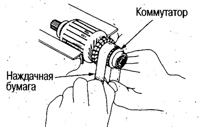
4. Check the commutator segments for wear, dirt and metal particles. If the segment surfaces are dirty or burnt, sand them with sandpaper #500 or #600.
5. Measure the depth of the mica. If the depth is less than the maximum, correct it with a hacksaw blade.
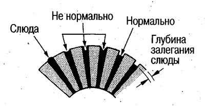
Mica depth:
- Standard: 0.4-0.5mm
- Limit: 0.15 mm
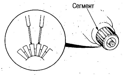
6. Make sure there is conductivity between each commutator segment.
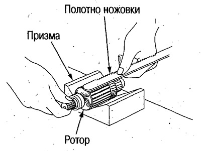
7. Mount the rotor on the prism, place the hacksaw blade parallel to the core and carefully turn the rotor. If the hacksaw blade is attracted to the core or vibrates, the rotor windings are shorted.
8. Check the conductivity between the commutator and the shaft, between the commutator and the core.
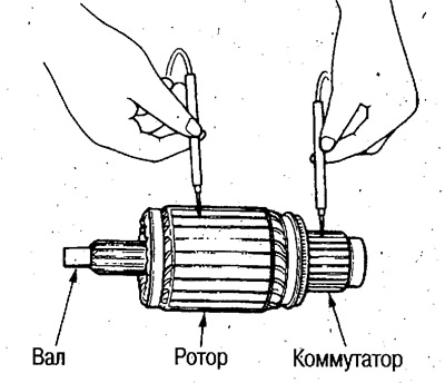
9. Using a megohmmeter with a standard voltage of 500V, measure the insulation resistance between the commutator and the core.
- Standard resistance: 0.1 MΩ (under voltage above 500V)